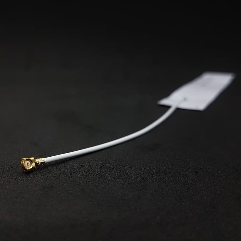
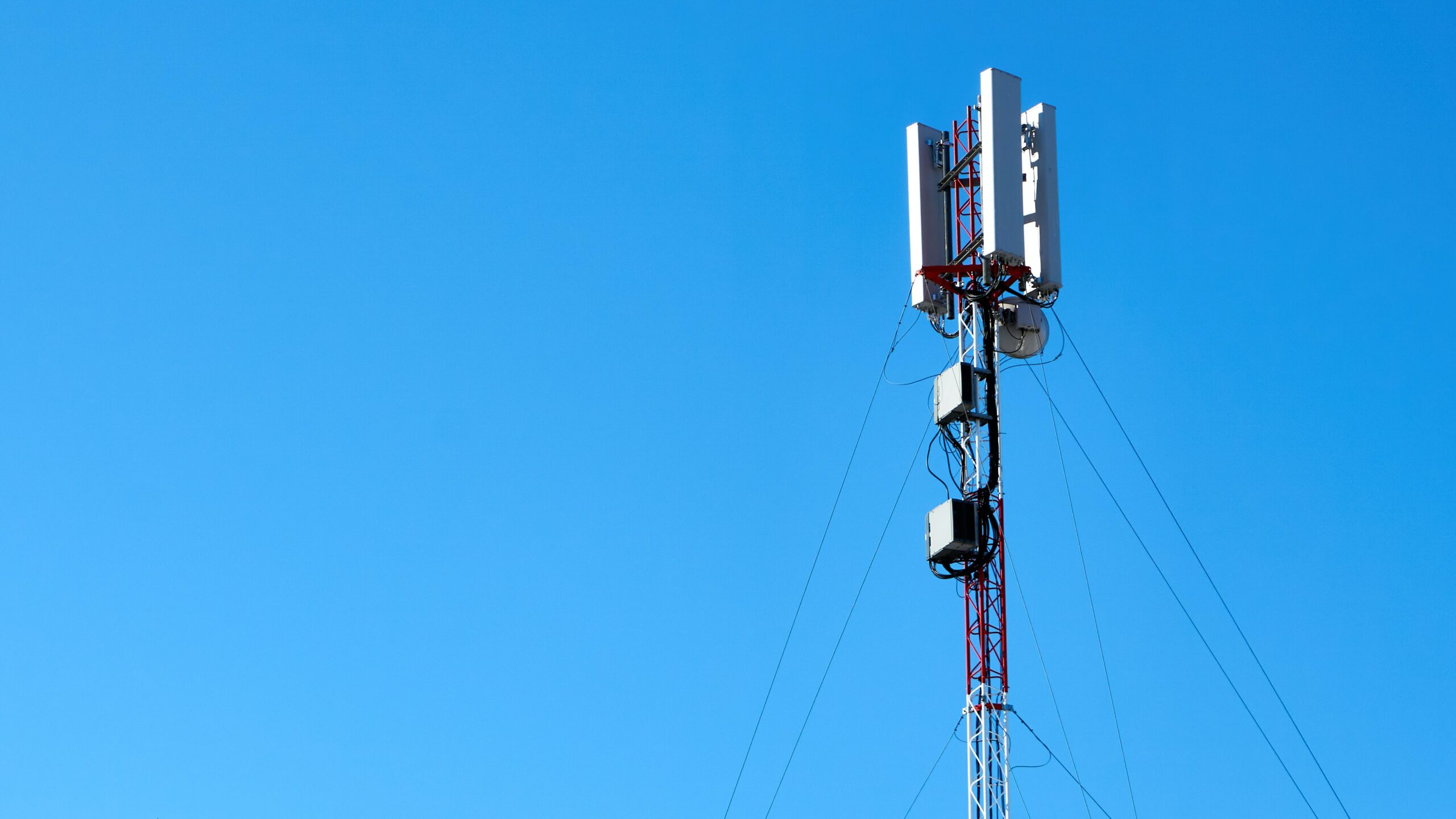
Photo by Vyacheslav Shatskiy on Unsplash
What is LTE Antenna?
Every single Internet of Things (IoT) device needs an antenna. The importance of an IoT product’s antenna cannot be overstated. It is the interface to the outside world. The antenna is one part of a system that conveys RF energy from a transmitter to a receiver. The antenna is crucial: it may make or break the communication with your devices. A good antenna will give you a good wireless range. A bad antenna may cause your devices to not even be reachable in the field.
IoT devices are typically small and often have a severely limited power budget to operate for long periods from a small energy source such as a primary coin cell. An antenna that may be suitable on paper is not guaranteed to perform well in practice. Proper selection and design-in are both essential to ensure a reliable wireless connection, covering the desired communication distance, while driving the antenna at the lowest possible input power to minimize demand on the device’s precious energy supply.
What are the Points to Consider in Antenna Selection?
Among the challenges that must be dealt with, selecting and integrating a suitable antenna has a significant impact on the RF-subsystem and consequently affects the system performance in terms of communication range, overall power consumption, and battery life.
To choose an antenna, the search can be focused on according to frequency range or wireless standard. Antennas are available for single-band applications or multi-band antennas designed for multiple feeds.
What are the LTE Antenna Types?
| Type of antenna | Examples | Applications |
|---|---|---|
| Wire Antennas | Dipole antenna, Monopole antenna, Helix antenna, Loop antenna | Personal applications, buildings, ships, automobiles, space crafts |
| Aperture Antennas | Waveguide (opening), Horn antenna | Flush-mounted applications, air-craft, space craft |
| Reflector Antennas | Parabolic reflectors, Corner reflectors | Microwave communication, satellite tracking, radio astronomy |
| Lens Antennas | Convex-plane, Concave-plane, Convex-convex, Concaveconcave lenses | Used for very highfrequency applications |
| Micro strip Antennas | Circular-shaped, Rectangularshaped metallic patch above the ground plane | Air-craft, space-craft, satellites, missiles, cars, mobile phones etc. |
| Array Antennas | Yagi-Uda antenna, Micro strip patch array, Aperture array, Slotted wave guide array | Used for very high gain applications, mostly when needs to control the radiation pattern |
Check out the antennas you can use in IoT projects

Important Parameters to Choose
- Shape and size of antenna
- To check Mounting option, whether it is RF connector mount, or PCB mount etc.
- Frequency of operation
- Coverage requirement
- Omni-directional or directional operation
- Gain of Antenna
Understanding LTE Signal Strength Values
Below are explanations of the LTE signal strength values:
- SINR/SNR – The signal-to-noise ratio of the given signal. The higher the SNR the better your signal quality will be. The SNR reading will be automatically calculated by the base station in dB.
- RSRP – The average power received from a single Reference signal, and Its typical range is around -44dbm (good) to -140dbm(bad).
- RSRQ – In dB, Indicates quality of the received signal, and its the ratio of usable signal to noise and interference measured in dBm. RSRQ=RSRP-RSSI.
- RSCP — In the UMTS cellular communication system, Received Signal Code Power (RSCP) denotes the power measured by a receiver on a particular physical communication channel.
- RSSI – In dBm, The Receive Strength Signal Indicator measures the average total received power of the whole band.
What Causes a Poor Signal on an LTE Antenna?
There are many different factors that influence signal strength and quality; these factors include, but are not limited, to the following:
- Distance from the Cellular Tower
- Physical barriers (mountains, buildings, trains, etc.)
- Building Structures ( brick, concrete, metal roofs, etc.)
- Interference
- Network Issues
- Network Congestion
- Weather
Signal strength and signal quality numbers do not incorporate all of the relevant factors. Keep in mind that measurements of signal strength and signal quality for a specific moment do not reflect on the stability of a connection, as these values will vary as conditions change.
Interpreting Signal Values
Signal measurement values are provided by the cellular modules at any time. The following modules (also available on Sixfab) show how to interpret the signal strengths.
As a rough guide, it defines the following quality measure for the quality of the connection between the mentioned modules and the and cell tower:
| RF Quality | RSRP (dBm) | RSRQ (dB) | SINR(dB) |
|---|---|---|---|
| Excellent | >= -80 | >= -10 | >= 20 |
| Good | -80 to -90 | -10 to -15 | 13 to 20 |
| Fair to poor | -90 to -100 | -15 to -20 | 0 to 13 |
| No signal | < -100 | < -20 | <= 0 |
RSSI for LTE is a calculated from several other signal related measurements:
RSSI = wideband power = noise + serving cell power + interference power
| RF Quality | RSSI(dBm) | Description |
|---|---|---|
| Excellent | >-65 | Strong signal with maximum data speeds |
| Good | -65 to -75 | Strong signal with good data speeds |
| Fair | -75 to -85 | Fair but useful, fast and reliable data speeds may be attained, but marginal data with drop-outs is possible |
| Poor | -85 to -95 | The performance will drop drastically |
| No signal | <= -95 | Disconnection |
It should be noted that all reported measurement values will be evaluated individually.
Quectel BG96 Cat M1/NB1/EGPRS Module
For Quectel BG96 AT+QCSQ AT command can be used:
AT+QCSQ
This will return a string like: Check out the antennas you can use in IoT projects
+QCSQ: <sysmode> ,<value1> ,<value2> ,<value3> , <value4>
<sysmode> → A string type value indicating the service mode in which the MT will unsolicitedly report the signal strength
<value1> ,<value2> ,<value3> , <value4> → the following table lists the signal strength type corresponding to each service mode.
| <sysmode> | <value1> | <value2> | <value3> | <value4> |
|---|---|---|---|---|
| “NOSERVICE” | ||||
| “GSM” mode | <gsm_rssi> | |||
| “CAT-M1” mode | <lte_rssi> | <lte_rsrp> | <lte_sinr> | <lte_rsrq> |
| “CAT-NB1” mode | <lte_rssi> | <lte_rsrp> | <lte_sinr> | <lte_rsrq> |
<gsm_rssi>,<lte_rssi> : An integer indicating the received signal strength. These parameters are available for GSM and LTE mode respectively.
<lte_rsrp> : An integer indicating the reference signal received power (RSRP). This parameter is available for LTE mode.
<lte_sinr> : An integer indicating the signal to interference plus noise ratio (SINR). Logarithmic value of SINR. Values are in 1/5th of a dB. The range is 0-250 which translates to -20dB – +30dB.
<lte_rsrq> : An integer indicating the reference signal received quality (RSRQ) in dB.
Example:
For 2G mode RSSI is the only measure. RSSI is a negative value, and the closer to 0, the stronger the signal.
For CAT-M1 and CAT-NB1 there are many measures (RSSI, RSRP, SINR, RSRQ).
Quectel EC25 Mini PCle Module
For Quectel EC25 AT+CSQ AT command can be used.
The command indicates the received signal strength <rssi> and the channel bit error rate <ber>.
This will return a string like: +CSQ: <rssi>,<ber>
<rssi>
| 0 | -113dBm or less |
| 1 | -111dBm |
| 2…30 | -109dBm… -53dBm |
| 31 | -51dBm or greater |
| 99 | Not known or not detectable |
| 100 | -116dBm or less |
| 101 | -115dBm |
| 102…190 | -114dBm…-26dBm |
| 191 | -25dBm or greater |
| 199 | Not known or not detectable |
| 100~199 | Extended to be used in TD-SCDMA indicating received signal code power (RSCP) |
<ber>
| 0…7 | As RXQUAL values in the table in 3GPP TS 45.008 subclause 8.2.4 |
| 99 | Not known or not detectable |
Example:
The received signal strength is –63dBm and channel bit error rate is 99.
| Value | RSSI(dBm) | Condition |
|---|---|---|
| 2 | -109 | Marginal |
| 3 | -107 | Marginal |
| 4 | -105 | Marginal |
| 5 | -103 | Marginal |
| 6 | -101 | Marginal |
| 7 | -99 | Marginal |
| 8 | -97 | Marginal |
| 9 | -95 | Marginal |
| 10 | -93 | OK |
| 11 | -91 | OK |
| 12 | -89 | OK |
| 13 | -87 | OK |
| 14 | -85 | OK |
| 15 | -83 | Good |
| 16 | -81 | Good |
| 17 | -79 | Good |
| 18 | -77 | Good |
| 19 | -75 | Good |
| 20 | -73 | Excellent |
| 21 | -71 | Excellent |
| 22 | -69 | Excellent |
| 23 | -67 | Excellent |
| 24 | -65 | Excellent |
| 25 | -63 | Excellent |
| 26 | -61 | Excellent |
| 27 | -59 | Excellent |
| 28 | -57 | Excellent |
| 29 | -55 | Excellent |
| 30 | -53 | Excellent |
Telit LE910C1 Mini PCIe Module
AT+CSQ and AT+CESQ AT commands are available for the Telit LE910C1.
AT+CSQ – Signal Quality Execution command returns received signal strength indication and channel bit error rate from the MT.
+CSQ: <rssi>, <sq>
<rssi> – received signal strength indication (3GPP)
| 0 | (-113) dBm or less |
| 1 | (-111) dBm |
| 2..30 | (-109) dBm. (-53) dBm / 2 dBm per step |
| 31 | (-51 ) dBm or greater |
| 99 | Not known or not detectable |
<rssi> – received signal strength indication (TDSCDMA)
| 100 | (-116) dBm or less |
| 101 | (-115) dBm |
| 102…191 | (-114…-26) dBm |
| 191 | (-25) dBm or greater |
| 199 | Not known or not detectable |
<sq> – signal quality – as mentioned below:
2G (GSM) – RXQUAL [bit error rate (in percent)]
| 0 | less than 0.2% |
| 1 | 0.2% to 0.4% |
| 2 | 0.4% to 0.8% |
| 3 | 0.8% to 1.6% |
| 4 | 1.6% to 3.2% |
| 5 | 3.2% to 6.4% |
| 6 | 6.4% to 12.8% |
| 7 | more than 12.8% |
| 99 | not known or not detectable |
3G (UTRAN) – ECIO(dBm)
| 0 | (-1) to (0) |
| 1 | (-5) to (-2) |
| 2 | (-8) to (-6) |
| 3 | (-11) to (-9) |
| 4 | (-15) to (-12) |
| 5 | (-18) to (-16) |
| 6 | (-22) to (-19) |
| 7 | (-24) to (-23) |
| 99 | not known or not detectable |
4G (LTE) – RSRQ(dBm)
| 0 | (-4) to (-3) |
| 1 | (-6) to (-5) |
| 2 | (-8) to (-7) |
| 3 | (-10) to (-9) |
| 4 | (-13) to (-11) |
| 5 | (-15) to (-14) |
| 6 | (-17) to (-16) |
| 7 | (-19) to (-18) |
| 99 | not known or not detectable |
AT+CESQ – Execution command returns received signal quality parameters according to the network on which the module
is registered.
The execution command returns the following message. Its format depends on the network on which the module is registered.+CESQ: <rxlev>,<ber>,<rscp>,<ecno>,<rsrq>,<rsrp>
<rxlev> – received received signal strength level (see 3GPP TS 45.008 subclause 8.1.4)
| 0 | rssi < -110 dBm |
| 1 | -110 dBm ≤ rssi < -109 dBm |
| 2 | -109 dBm ≤ rssi < -108 dBm |
| .. | … |
| 61 | -50 dBm ≤ rssi < -49 dBm |
| 62 | -49 dBm ≤ rssi < -48 dBm |
| 63 | -48 dBm ≤ rssi |
| 99 | not known or not detectable or if the current serving cell is not a GERAN cell |
<ber> – bit error rate (in percent)
| 0…7 | As RXQUAL values in the table in 3GPP TS 45.008 subclause 8.2.4 |
| 99 | not known or not detectable or if the current serving cell is not a GERAN cell |
<rscp> – received signal code power (see 3GPP TS 25.133 subclause 9.1.1.3 and 3GPP TS 25.123 subclause 9.1.1.1.3).
| 0 | rscp < -120 dBm |
| 1 | -120 dBm ≤ rscp < -119 dBm |
| 2 | -119 dBm ≤ rscp < -118 dBm |
| … | … |
| 94 | -27 dBm ≤ rscp < -26 dBm |
| 95 | -26 dBm ≤ rscp < -25 dBm |
| 96 | -25 dBm ≤ rscp |
| 255 | not known or not detectable or if the current serving cell is not a UTRA cell |
<ecno> – ratio of the received energy per PN chip to the total
| 0 | Ec/Io < -24 dB |
| 1 | -24 dB ≤ Ec/Io < -23.5 dB |
| 2 | -23.5 dB ≤ Ec/Io < -23 dB |
| … | … |
| 47 | -1 dB ≤ Ec/Io < -0.5 dB |
| 48 | -0.5 dB ≤ Ec/Io < 0 dB |
| 49 | 0 dB ≤ Ec/Io |
| 255 | not known or not detectable or if the current serving cell is not a UTRA cell |
<rsrq> – reference signal received quality (see 3GPP TS 36.133 subclause 9.1.7).
| 0 | rsrq < -19.5 dB |
| 1 | -19.5 dB ≤ rsrq < -19 dB |
| 2 | -19 dB ≤ rsrq < -18.5 dB |
| .. | … |
| 32 | -4 dB ≤ rsrq < -3.5 dB |
| 33 | -3.5 dB ≤ rsrq < -3 dB |
| 34 | -3 dB ≤ rsrq |
| 255 | not known or not detectable detectable or if the current serving cell is not a EUTRA cell |
<rsrp> – type, reference signal received power (see 3GPP TS 36.133 subclause 9.1.4).
| 0 | rsrp < -140 dBm |
| 1 | -140 dBm ≤ rsrp < -139 dBm |
| 2 | -139 dBm ≤ rsrp < -138 dBm |
| … | … |
| 95 | -46 dBm ≤ rsrp < -45 dBm |
| 96 | -45 dBm ≤ rsrp < -44 dBm |
| 97 | -44 dBm ≤ rsrp |
| 255 | not known or not detectable or if the current serving cell is not a EUTRA cell |
Telit ME910C1-WW Mini PCle Module
AT+CSQ and AT+CESQ AT commands are available for the Telit LE910C1 module.
AT+CSQ – Signal Quality Execution command returns received signal strength indication and channel bit error rate from the MT.
2G Networks The execution command returns the following message: +CSQ: <rssi>, <ber>
<rssi> – received signal strength indication
| 0 | (-113) dBm or less |
| 1 | (-111) dBm |
| 2..30 | (-109) dBm. (-53) dBm / 2 dBm per step |
| 31 | (-51 ) dBm or greater |
| 99 | Not known or not detectable |
<ber> – bit error rate (in percent)
| 0 | less than 0.2% |
| 1 | 0.2% to 0.4% |
| 2 | 0.4% to 0.8% |
| 3 | 0.8% to 1.6% |
| 4 | 1.6% to 3.2% |
| 5 | 3.2% to 6.4% |
| 6 | 6.4% to 12.8% |
| 7 | more than 12.8% |
| 99 | not known or not detectable |
4G Networks The execution command returns the following message:+CSQ: <rssi>,<rsrq>
<rssi> – Received Signal Strength Indication.
For to be compliant with 3GPP TS27.007 specification, levels are mapped to range 0…31.
| 0 | (-113) dBm or less |
| 1 | (-111) dBm |
| 2..30 | (-109) dBm. (-53) dBm / 2 dBm per step |
| 31 | (-51 ) dBm or greater |
| 99 | Not known or not detectable |
<rsrq> – Reference Signal Received Quality.
For levels are mapped to range 0…7.
| 0 | -4…-3 dB |
| 1 | -6…-5 dB |
| 2 | -8…-7 dB |
| 3 | -10…-9 dB |
| 4 | -13…-11 dB |
| 5 | -15…-14 dB |
| 6 | -17…-16 dB |
| 7 | -19…-18 dB |
| 99 | not known or not detectable |
AT+CESQ – Execution command returns received signal quality parameters according to the network on which the module
is registered.
The execution command returns the following message. Its format depends on the network on which the module is registered.
2G Networks The execution command returns the following message:
+CESQ: <rxlev>,<ber>,255,255,255,255
LTE Networks The execution command returns the following message:
+CESQ: 99,99,255,255,<rsrq>,<rsrp>
<rxlev> – received signal strength level, see 3GPP TS 45.008 subclause 8.1.4.
| 0 | rssi < -110 dBm |
| 1 | -110 dBm ≤ rssi < -109 dBm |
| 2 | -109 dBm ≤ rssi < -108 dBm |
| … | … |
| 61 | -50 dBm ≤ rssi < -49 dBm |
| 62 | -49 dBm ≤ rssi < -48 dBm |
| 63 | 48 dBm ≤ rssi |
| 99 | not known or not detectable or if the current serving cell is not a GERAN cell |
<ber> – channel bit error rate.
| 0…7 | As RXQUAL values in the table in 3GPP TS 45.008 subclause 8.2.4 |
| 99 | not known or not detectable or if the current serving cell is not a GERAN cell |
<rsrq> – reference signal received quality, see 3GPP TS 36.133 subclause 9.1.7.
| 0 | rsrq < -19.5 dB |
| 1 | -19.5 dB ≤ rsrq < -19 dB |
| 2 | -19 dB ≤ rsrq < -18.5 dB |
| .. | … |
| 32 | -4 dB ≤ rsrq < -3.5 dB |
| 33 | -3.5 dB ≤ rsrq < -3 dB |
| 34 | -3 dB ≤ rsrq |
| 255 | not known or not detectable detectable or if the current serving cell is not a EUTRA cell |
<rsrp> – type, reference signal received power (see 3GPP TS 36.133 subclause 9.1.4).
| 0 | rsrp < -140 dBm |
| 1 | -140 dBm ≤ rsrp < -139 dBm |
| 2 | -139 dBm ≤ rsrp < -138 dBm |
| … | … |
| 95 | -46 dBm ≤ rsrp < -45 dBm |
| 96 | -45 dBm ≤ rsrp < -44 dBm |
| 97 | -44 dBm ≤ rsrp |
| 255 | not known or not detectable or if the current serving cell is not a EUTRA cell |


