GPS Tracker with 3G, 4G/LTE shield

In this tutorial we will learn how to get GPS data using 3G, 4G/LTE shield.

GPS(Global Positioning System) also known as NavStar indicates the position of an individual on the earth. The Satellites orbiting around the earth sends precise details of their positions at a regular interval of time. Once information are received by a GPS receiver, a GPS receiver can pinpoint the location.

There are also navigation systems which support in their in specific regions like GLONASS provided in Russia.

For this tutorial we will need
a. Raspberry Pi
b. 3G, 4G/LTE Shield
c. 3G, 4G/LTE module (for 3G UC20 and for 4G EC25 is used)
d. PCB Mobile Antenna (2x)
e. GPS Antenna
Here it goes


1. Connect EC25 module to the shield.

Jpeg

Sixfab 3G,4G/LTE shield and EC25 module

Jpeg

EC25 module connected to shield

2. Insert SIM in the sim slot

Jpeg

Inserting Sim

3. Connect the shield to a Raspberry Pi

Jpeg

Shield attached to Raspberry Pi 3

4. Now connect antenna to the ports as shown in the figure below

Jpeg

Connecting Antenna

5. Now connect a microUSB to the shield from Raspberry Pi.
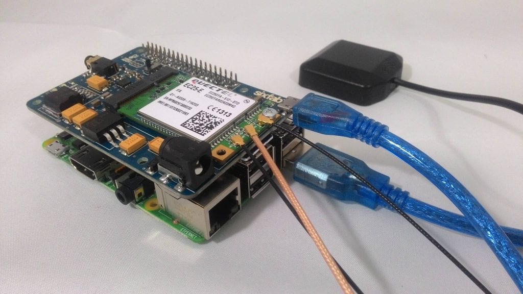
Jpeg

Tracker setup

So the setup is ready for tracking.

Now we can power our Raspberry Pi and control trough terminal as done in previous tutorials.

GPS data can be obtained either using minicom or writing your own python code.

***************************************MINICOM***************************************

6a. Type

minicom -s

to bring up the minicom settings screen

7Opening minicom

6b. Select Serial port setup

8

minicom configuration screen

6c. Make the following changes

Serial Device : /dev/ttyUSB2

Hardware Flow Control : No

9

Configuring Serial Port Setup

6d. Now Exit from the setting screen

10

Exiting from minicom configuration screen

6e. Check connectivity with ‘AT’ which in response gives ‘OK’ or returns an error.
11

minicom screen

12

minicom screen

6f. Now type ‘AT+QGPS=1’ turns on the GNSS(Global Navigation Satellite Systems) engine.

13

minicom screen

6g. Again go to minicom settings > Serial Port Setup and make the following changes.

Serial device : /dev/ttyUSB1  

Hardware Flow Control : No

14

Configuring Serial Port Setup

6h. Exit from the settings screen which will bring up following screen with GPS NMEA data.

15

GPS Data


****************************************************Pyhton****************************************************

Now we will write a python code to obtain the GPS values

7a. First create a python file by the following command.

sudo nano gpstest.py

16

Opening .py file


7b. Now type the following python code in the file and save it. You may get the code from github.

from time import sleep
import serial

portwrite = "/dev/ttyUSB2"
port = "/dev/ttyUSB1"

def parseGPS(data):
    print "raw:", data #prints raw data
    if data[0:6] == "$GPRMC":
        sdata = data.split(",")
        if sdata[2] == 'V':
            print "no satellite data available"
            return
        print "-----Parsing GPRMC-----"
        time = sdata[1][0:2] + ":" + sdata[1][2:4] + ":" + sdata[1][4:6]
        lat = decode(sdata[3]) #latitude
        dirLat = sdata[4]      #latitude direction N/S
        lon = decode(sdata[5]) #longitute
        dirLon = sdata[6]      #longitude direction E/W
        speed = sdata[7]       #Speed in knots
        trCourse = sdata[8]    #True course
        date = sdata[9][0:2] + "/" + sdata[9][2:4] + "/" + sdata[9][4:6]
                           #date
        variation = sdata[10]  #variation
        degreeChecksum = sdata[11]
        dc = degreeChecksum.split("*")
        degree = dc[0]        #degree
        checksum = dc[1]      #checksum
        print "time : %s, latitude : %s(%s), longitude : %s(%s), speed : %s, True Course : %s, Date : %s, Magnetic Variation : %s(%s),Checksum : %s "%    (time,lat,dirLat,lon,dirLon,speed,trCourse,date,variation,degree,checksum)
    else:
        print "Printed data is ",data[0:6]
def decode(coord):
    #Converts DDDMM.MMMMM -> DD deg MM.MMMMM min
    x = coord.split(".")
    head = x[0]
    tail = x[1]
    deg = head[0:-2]
    min = head[-2:]
    return deg + " deg " + min + "." + tail + " min"

print "Connecting port"
serw = serial.Serial(portwrite, baudrate = 115200, timeout = 1)
serw.write('AT+QGPS=1\r')
serw.close()
sleep(0.5)

print "Receiving GPS data"
ser = serial.Serial(port, baudrate = 115200, timeout = 0.5)
while True:
   data = ser.readline()
   parseGPS(data)


7c. After saving it we will run the code with following command.

sudo python gpstest.py

18

Running .py file

19

GPS data received

Similarly depending on the code required values from the data can be extracted.


39 thoughts

  1. I’m getting the broken pipe error when running the serial.Serial function from the script, any idea on this one? It works fine from the minicom though.

  2. I am using same code as mention, but getting following error.
    Can you please guide.

    [email protected]:~ $ sudo python gps.py
    Connecting port
    Receiving GPS data
    raw: $GPVTG,,T,,M,,N,,K,N*2C

    —–Parsing GPRMC—–
    Traceback (most recent call last):
    File “gps.py”, line 48, in
    parseGPS(data)
    File “gps.py”, line 14, in parseGPS
    time = sdata[1][0:2] + “:” + sdata[1][2:4] + “:” + sdata[1][4:6]
    UnboundLocalError: local variable ‘sdata’ referenced before assignment
    [email protected]:~ $

    • The issue is related to the indentation of the code:
      – lines 12 and 13 should be more indented in order to be considered part of the “if” statement at line 11
      – lines 14 to 29 should be indented at the same level as line 10 and 11. Doing that will make lines 14 to 29 part of the same block as sdata (line 10) and thus will resolve the issue.

      I also had to change “degreeChecksum” at line 25 from index 11 to 12

  3. When my pi loses power it seems the minicom setting are resetting. how to make theses setting persistent?

  4. I’m trying to enable gpsoneXTRA on the EC25-E and I’m having a hard time with it. When I say enable XTRA I’m actually referring to the process of uploading the xtra2.bin file into the EC25’s RAM module.

    The process that’s failing on me is composed of the following steps:
    1. Running AT+QFUPL=”RAM:xtra2.bin”,<>,<> – by the way, the serial port has the HW control enabled.
    2. Get the CONNECT message.
    3. Sending the file and when it finishes sending it, I don’t get any OK from the module. This is where it fails. Even the keyboard is “jammed” for a couple of seconds before I regain the control over it.

    Do you have any experience regarding this? There’s absolutely nothing on the web to help me out with this, so I’m asking you since you already wrote a tutorial on the EC25-E for the GPS.

    Thanks

  5. Hi Saeed, I’ve also encounter GPS issues where i couldn’t run the code. Here’s the error. I’m using the IoT App. Shield with BG96 module. thanks

    There are two errors
    1. Traceback (most recent call last):
    File “/usr/lib/python3/dist-packages/serial/serialposix.py”, line 265, in open
    self.fd = os.open(self.portstr, os.O_RDWR | os.O_NOCTTY | os.O_NONBLOCK)
    FileNotFoundError: [Errno 2] No such file or directory: ‘/dev/ttyUSB2’

    During handling of the above exception, another exception occurred:

    Traceback (most recent call last):
    File “/home/pi/gpstest.py”, line 42, in
    serw = serial.Serial(portwrite, baudrate = 115200, timeout = 1)
    File “/usr/lib/python3/dist-packages/serial/serialutil.py”, line 236, in __init__
    self.open()
    File “/usr/lib/python3/dist-packages/serial/serialposix.py”, line 268, in open
    raise SerialException(msg.errno, “could not open port {}: {}”.format(self._port, msg))
    serial.serialutil.SerialException: [Errno 2] could not open port /dev/ttyUSB2: [Errno 2] No such file or directory: ‘/dev/ttyUSB2’
    >>>

    2. Traceback (most recent call last):
    File “/home/pi/gpstest.py”, line 43, in
    serw.write(‘AT+QGPS=1\r’)
    File “/usr/lib/python3/dist-packages/serial/serialposix.py”, line 518, in write
    d = to_bytes(data)
    File “/usr/lib/python3/dist-packages/serial/serialutil.py”, line 63, in to_bytes
    raise TypeError(‘unicode strings are not supported, please encode to bytes: {!r}’.format(seq))
    TypeError: unicode strings are not supported, please encode to bytes: ‘AT+QGPS=1\r’

    Is there any way to fix this? Thank you.

  6. Hi, I’v trying to set this up using UART but I can’t manage to read any data.

    I’ve wired the UART and RESISTORS under the board, checked my 8 and 10 pins on the rpi, but I can’t read anything from the board.

    Any tip ?

    Regards

  7. I am having the same issue as Christopher’s issue #3:

    Traceback (most recent call last):
    File “/home/pi/Applications/Sixfab_RPi_CellularIoT_App_Shield/gps_test.py”, line 43, in
    serw.write(‘AT+QGPS=1\r’)
    File “/usr/lib/python3/dist-packages/serial/serialposix.py”, line 518, in write
    d = to_bytes(data)
    File “/usr/lib/python3/dist-packages/serial/serialutil.py”, line 63, in to_bytes
    raise TypeError(‘unicode strings are not supported, please encode to bytes: {!r}’.format(seq))
    TypeError: unicode strings are not supported, please encode to bytes: ‘AT+QGPS=1\r’

    Can anybody help?

      • Hi Saeed, I’m still experiencing problems same with Peter. Sorry I’m a newbie trying to use GPS.. can you show me which is the library for GNSS data?

    • Hi Peter, I’ve fixed with the unicode strings are not supported issue, turns out you need to encode the ‘AT+QGPS=1\r’.
      Here’s the fix:

      serw.write(str.encode(‘AT+QGPS=1\r’))

      Hope this helps.

  8. Hello,
    I am missing the altitude in the GPS data. Is there a possibility to get it ?

    Regards

    Uli

  9. The GNSS antenna connector provides power supply for active antenna? Or need to be enable (hardware jumpers)?

    • OK, after some check I see that BG96 Iot board has NO power supply enabled. Need to solder a jump on the board. Now it’s working fine.

  10. Hello when i try run de code, i receive the following error.

    Traceback (most recent call last):
    File “gpstest.py”, line 2, in
    import serial
    ImportError: No module named serial

    Pleas, can you help me.

    Thank you

  11. Saeed
    I can not get my pi to read the raw GPS data.

    I have tried the minicom settings a few different times, I have done this in the past and it works. But on the pi 3 B+ no luck. Suggestions?

    • Which antenna are you using?
      What is the location(indoor/outdoor) of your use?
      While trying with minicom
      Does AT+QGPS=1 answer as OK

      What do you get in /dev/ttyUSB1?

      • So I wrote this script to sent the AT command on reboot

        sudo nano at.py

        import serial
        from sys import exit

        ser=serial.Serial(‘/dev/ttyUSB2’, 115200)
        ser.write(“AT+QGPS=1\r”)

        while True:
        response = ser.readline()
        print “python printed:”, response

        exit()

        then run in crontab @reboot.
        Seems to be working now.

  12. I am using the Pulse Electronics antenna
    LTE Main & Diversity & GNSS Triple Port u.FL Antenna – 100mm

    I am indoor with a GPS booster.
    I have a USB gps and it works fine connected to the pi.

    When I do AT+QGPS=1
    I get the following

    OK

    +QGPSURC: “xtradataexpire”,0,”1980/01/05,19:00:00″

    In ttyUSB1 I get no return

  13. Hello,

    Is it possible to use gpsd with the hat ? If so can you provide an example.
    In the config of gpsd we can provide only one serial port, so I don’t know if I shoudl put ttyUSB1 or ttyUSB2 ?

  14. Hi!
    I’m using 3G/4G&LTE base HAT with EC25 LTE module. We get the internet connection working but we don’t get the GNSS working at all. I did the same steps that you have posted as instructions but when I open the minicom and type the AT I get OK but after that when I try to switch the GPS on by typing AT+QGPS=1, Ijust get ERROR. And this hapens every time and no mater what I type in it just says ERROR but to just AT it always says Ok. Can you help me whith this issue?

  15. I have followed your steps until the command AT is required

    then when i Type it I do not see the letters “AT”, and when I press enter I receive OK. Then when I input the AT+QGPS=1 I receive an error.

    +CME ERROR: 504

    any help please?

    • Hello,
      Could you please try with other port. CME error 504 means a session is ongoing. Could you please check from other port?
      Best regards.

Leave a Reply

Your email address will not be published. Required fields are marked *