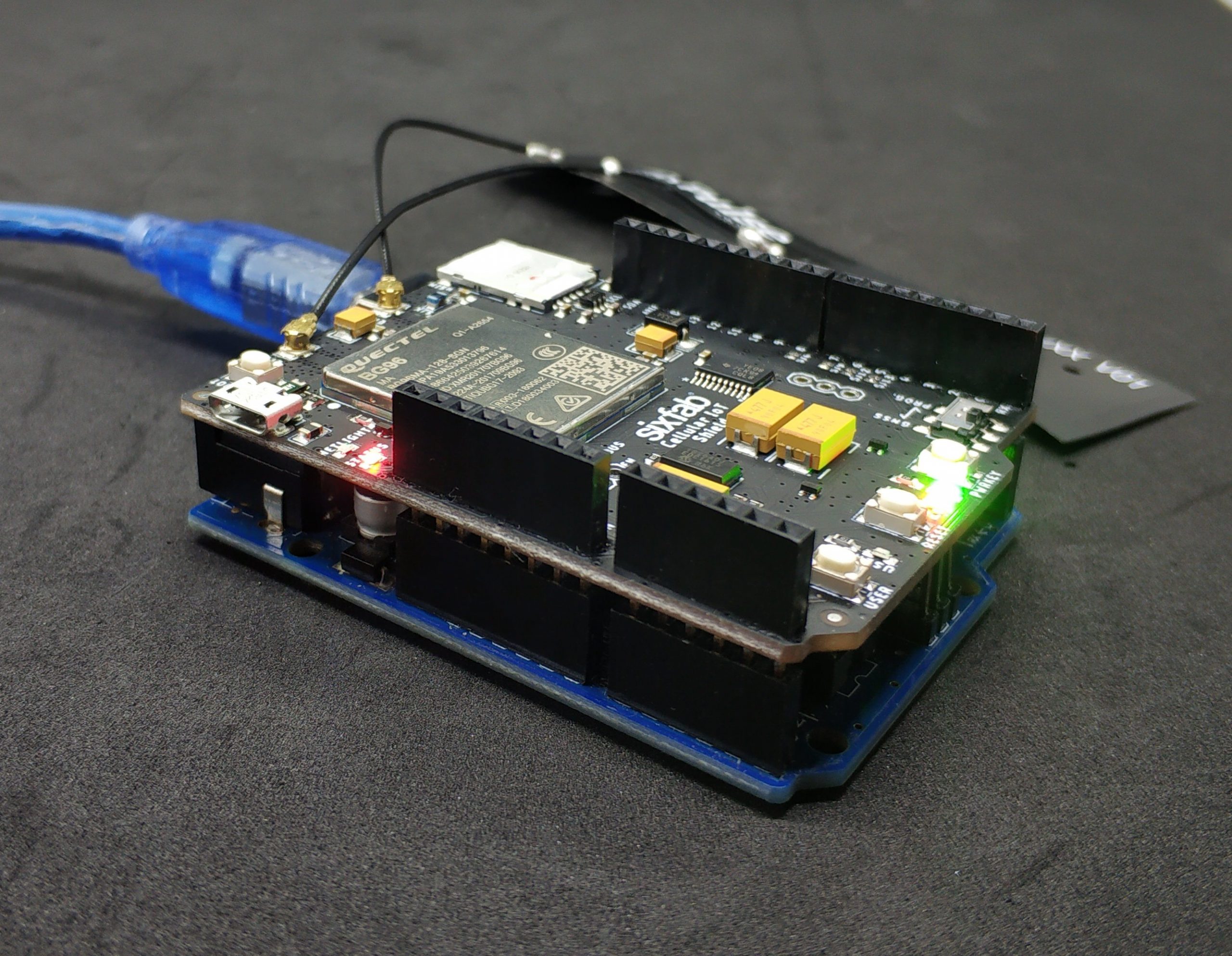
Sixfab came up with Arduino Cellular IoT Shield. This shield is a lighter version of our previous Arduino Cellular IoT Application Shield, where both uses Quectel BG96 module. The major difference is the peripheral sensors, this new shield doesn’t contain any sensors on it which makes it lighter.
What is the feature of this Shield?
This Cellular IoT Shield contains Quectel BG96 which has combined LTE technologies Cat.M1, Cat.NB1 and eGPRS. It also supports GPS too.
Preconfiguration
Before we start working with the Shield, let us set up our router settings.
Your router needs port forwarding for UDP connection. Note down the IP address of your router and UDP port number(We will need it later).
Hardware Setup
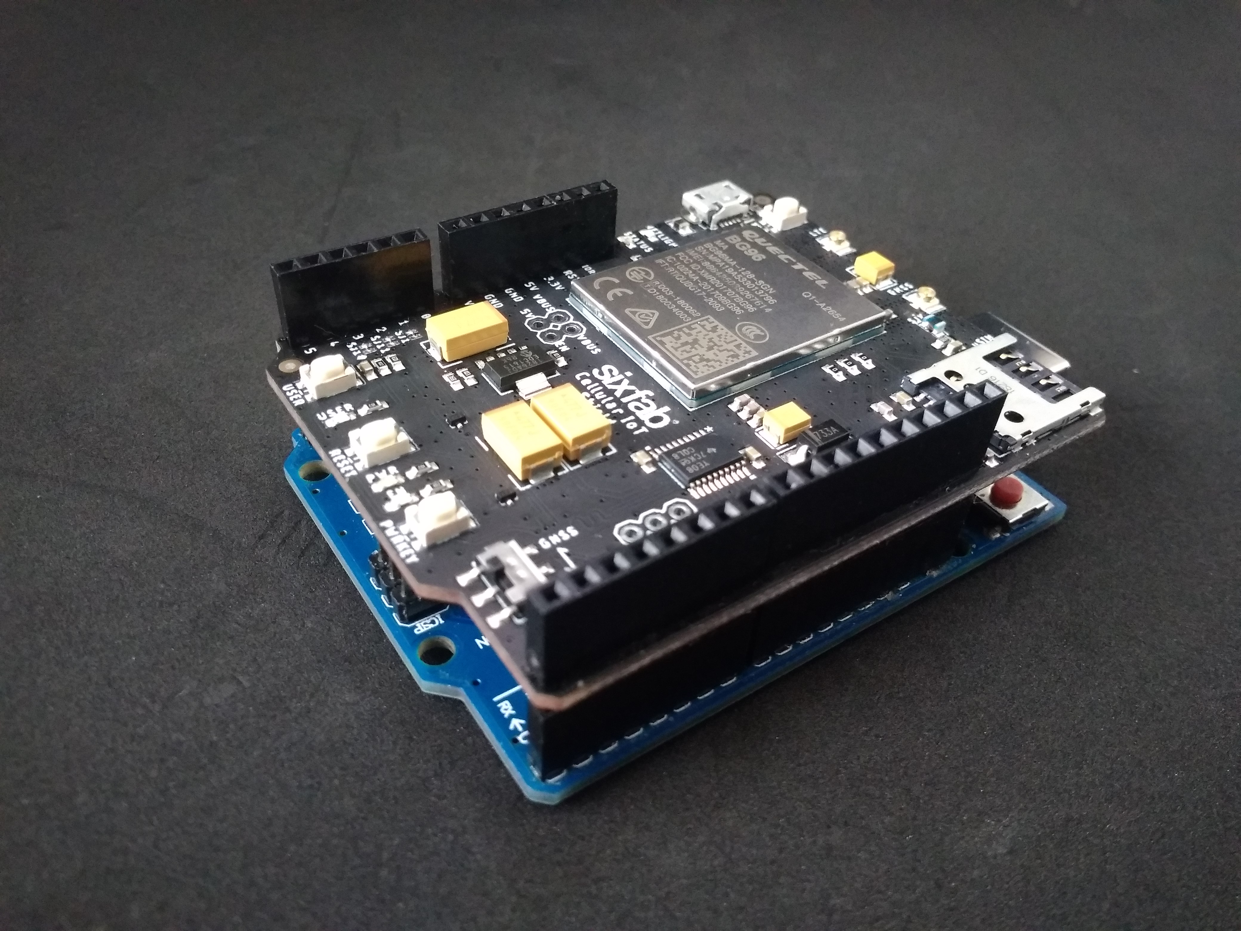
- Attach the Cellular IoT Shield to your Arduino Uno (Any Arduino with similar pinout as Arduino UNO can be used).

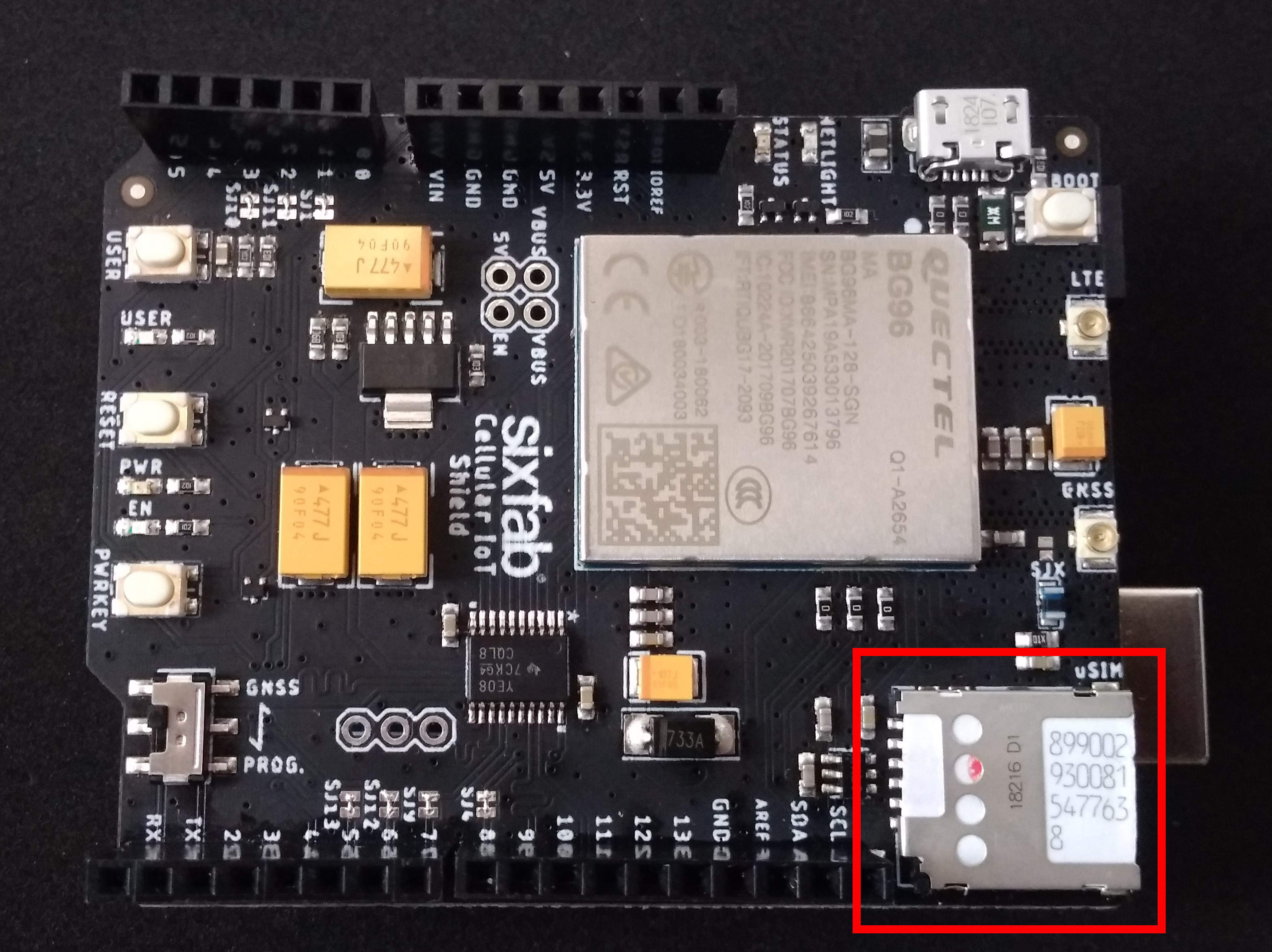
- Insert the Sim.

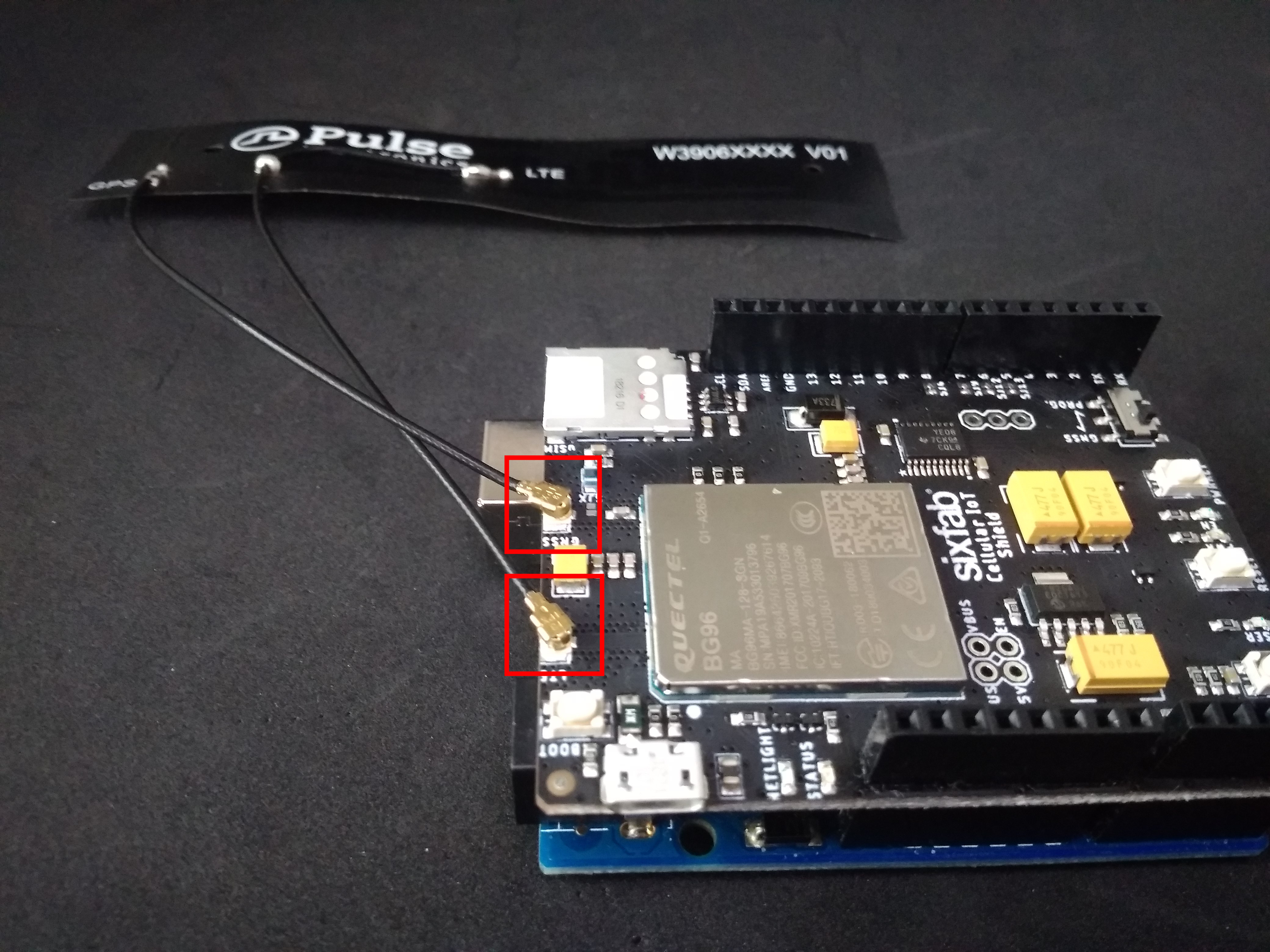
- Plug the antenna. You will need one LTE antenna with u.FL for this tutorial. Here, I am using LTE – GNSS Dual u.FL Antenna – 100mm, as it comes with the shield.

- Now plug your Arduino to your laptop/desktop.
Software Setup
Now we are ready to start.
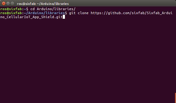
- Clone the library from github to your Arduino/libraries directory.
git clone https://github.com/sixfab/Sixfab_Arduino_CellularIoT_App_Shield.git
 ORYou can download .zip format from github repo and extract it in your Arduino/Libraries directory.
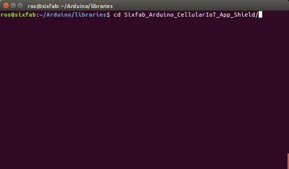
 - Now get into the cloned directory.
cd Sixfab_Arduino_CellularIoT_App_Shield/
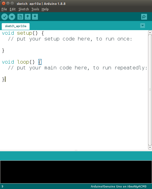
- Now open your Arduino IDE.

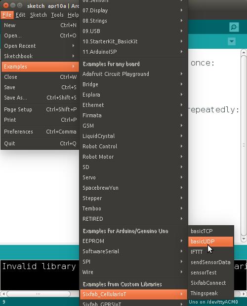
- Go to File > Examples > Sixfab_CellularIoT and click basicUDP.
- This will bring up basicUDP.ino code.
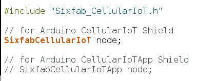
- Make sure you have uncommented
SixfabCellularIoT node;
and commented
SixfabCellularIoTApp node;

- Here, you will see following two lines.
your_ip = "xx.xx.xx.xx";
your_port = "xxxx";
You have to replace these information with your own which you have set in the preconfiguration step that is, the routers IP and the UDP port address.
- Now save the sketch.
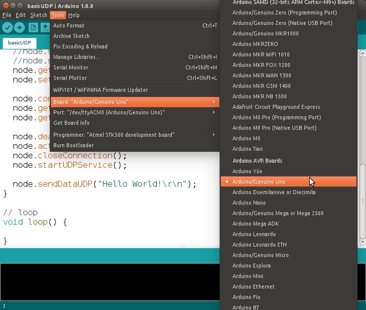
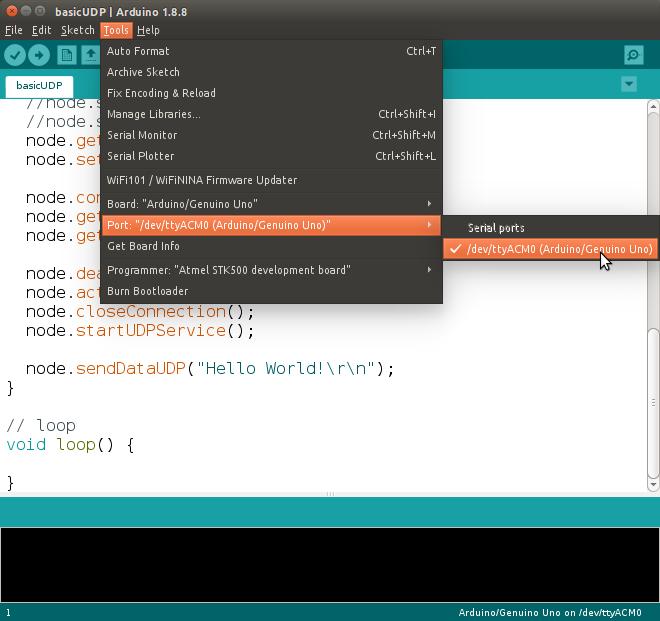
- Before uploading the code to your Arduino, go to Tools select Board and Port. For us Board is Arduino/Genuino Uno and Port is /dev/ttyACM0. Port will be different for Windows users.


- Now Upload the code to your Arduino.
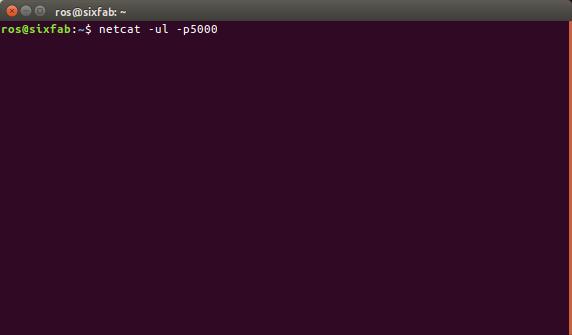
- To listen the UDP Data that will be sent over UDP, open a new terminal and type
netcat -ul -p5000
Here 5000 is my port number. Replace it with your port number. (This is to be done in the Device where you have directed the UDP port during the preconfiguration step)
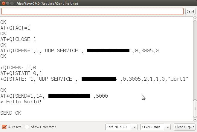
- Open the Serial Monitor And you will see the following screen.

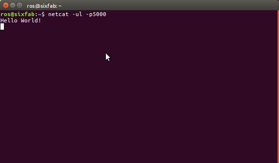
- Once the UDP Data is sent successfully. You will be able to see the data from your terminal.

Hence, We are done with the tutorial here. Please write suggestions, questions and feedback in the comment section below.


 ORYou can download .zip format from