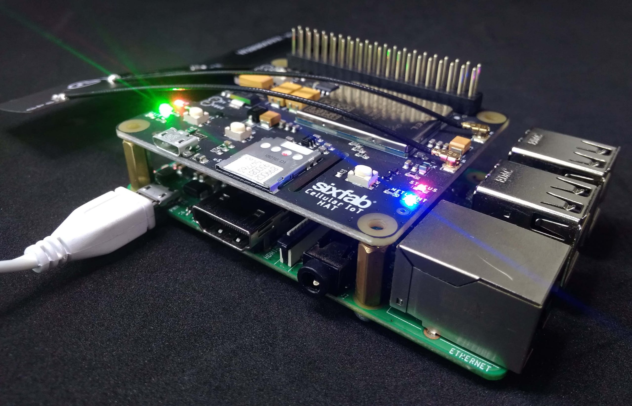
Sixfab came up with Raspberry Pi Cellular IoT HAT. This time it is a Hat rather than a shield. To be more specific this HAT is lighter version of our previous Raspberry Pi Cellular IoT Application Shield, where both uses Quectel BG96 module. The major difference is the peripheral sensors, the HAT doesn’t contain any sensors on it.
What is the feature of this HAT?
This HAT contains Quectel BG96 which has combined LTE technologies Cat.M1, Cat.NB1 and eGPRS.
It also supports GPS.
Preconfiguration
Before we start working with the HAT, let us setup our router settings and Raspberry pi.
Your router needs port forwarding for UDP connection. You can do it by following Port Forwarding Tutorial. Note down the IP address of your router and UDP port number.
The Serial port hardware of your Raspberry Pi should be enabled and Login shell to be accessible over serial should be disabled. This can be done from raspi-config.
Hardware Setup
- Attach the Cellular IoT HAT to your Raspberry Pi.
- Insert the Sim.
- Plug the antenna. You will need one LTE antenna with u.FL for this tutorial. Here, I am using LTE Full Band PCB Antenna.
Software Setup
Now we are ready to start.
Download/clone the library from github
git clone https://github.com/sixfab/Sixfab_RPi_CellularIoT_App_Shield.git
Now get into the cloned directory.
cd Sixfab_RPi_CellularIoT_Library
Now install the library
sudo python3 setup.py install
Make sure you are installing it with python3.
Now goto sample directory
cd sample/
Now open the basicUDP.py script.
nano basicUDP.py
Here, you will see following two lines.
your_ip = "xx.xx.xx.xx"; your_port = "xxxx";
You have to replace these information with your own which have set in the preconfiguration step that is the routers IP and the UDP port address.
Check if the
node = cellulariot.CellularIoT()
is uncommented.
Now save the python script and run with
python3 basicUDP.py
Just before running the script open a new terminal in your laptop and type
netcat -ul -p5000
Here 5000 is my port number. Replace it with your port number. (This is to be done in the Device where you have directed the UDP port during the preconfiguration step)
Here you can see the Data that has been sent over UDP.
Hence, We are done with the tutorial here. Please write suggestions, questions and feedback in the comment section below.
Hi !
When I follow this tutorial for the Raspberry Pi Cellular IoT HAT – LTE-M & NB-IoT & eGPRS, the program loop at “AT+CGATT?”. Any idea of what could be wrong with my device ?
Your Sim is not connecting to the Base station. Which band and Mode are you using for the connection?
Hi Saeed, thank you for your response.
However it is.. I didn’t modify the band : node.setGSMBand(node.GSM_900)
node.setCATM1Band(node.LTE_B5)
node.setNBIoTBand(node.LTE_B20)
I’m located in Singapore. Could it be the problem ?
OK, I think I understand what you mean. I’ve changed the band to GSM_1800 as I’m using a Sim card operator : M1 and APN: sunsurf.
I use the GSM_MODE.
Unfortunately, it still doesn’t work. But thank you for your response, I will research a solution.
Hi, Since you are using LTE CAT M1,
use
node.setMode(CATM1_MODE)
node.setCATM1Band(node.LTE_B5) #Make sure B5 supports in your location. If you don’t know your band you can use LTE_CATM1_ANY instead.
Hi again,
I tried with CATM1_MODE and LTE_CATM1_ANY and it still doesn’t work. Is there other test I could try to find my problem ?
Write
node.getSignalQuality()
node.getQueryNetworkInfo()
before
node.connectToOperator()
Please share the output.
Here is the output. I have tried with GSM_MODE but it’s the same result.
Sixfab Raspberry Pi Cellular IoT Shield Class initialized!
BG96 module disabled!
BG96 module enabled!
BG96 module powered up!
ATE1
ATE1
ATE1
OK
AT+CGSN
AT+CGSN
866425039281441
OK
AT+CGMR
AT+CGMR
BG96MAR02A07M1G
OK
AT+CGMM
AT+CGMM
BG96
OK
AT+QCFG=”band”,2,0,0
OK
AT+QCFG=”band”,0,400A0E189F,0
OK
AT+QCFG=”band”,0,0,80000
OK
AT+QCFG=”band”
AT+QCFG=”band”
+QCFG: “band”,0x2,0x400a0e189f,0x80000
OK
AT+QCFG=”nwscanseq”,02,1
OK
AT+QCFG=”nwscanmode”,3,1
OK
AT+QCFG=”iotopmode”,0,1
OK
Modem configuration : CATM1_MODE
AT+CSQ
AT+CSQ
+CSQ: 99,99
OK
AT+QNWINFO
AT+QNWINFO
+QNWINFO: No Service
OK
Trying to connect base station of operator…
AT+CGATT?
AT+CGATT?
I am also getting the No Service message. We’re you ever able to resolve your issue?
I have an issue with getting my GPS location with the IoT HAT.
So I used the Turn on GPS command “turnOnGNSS” it turns with OK,
next I use the command “getLatitude” it turns with error that means it can’t loc the GPS.
But when I use the minicom I can see the GPS sending location normally, why ? is it because the cellulariot.py doesn’t have the ttyUSB1 connected ?
Could you please share the error details?
Hi !
Is it possible to transmit larger data (eg photos / videos?
Thank you.
Have a nice day,
Micka
Hi.
Yes it possible but it is related to the internet speed of your SIM card.
I am getting File Not Found Error – No such file or directory: ‘/dev/ttyS0’
there are no ttyS* devices in /dev directory.
I have also run the ppp installer tutorial here.
Any help is appreciated. Thanks
How did you enable the serial connection ?
It should normally be done (as an easy method)
sudo raspi-config
Select option 5, Interfacing options,
then option P6, Serial,
Select No to Serial Console
Select Yes to Serial Port.
Reboot.
Can you share the output of
ls /dev/serial/by-id/
?I was getting a similar error.
I have enabled serial and its at ttyUSB0. Where to apply this setting to change ttyS0?
ls /dev/serial/by-id
total 0
lrwxrwxrwx 1 root root 13 Jul 3 09:55 usb-FTDI_TTL232R-3V3_FTBHKTHS-if00-port0 -> ../../ttyUSB0