Description
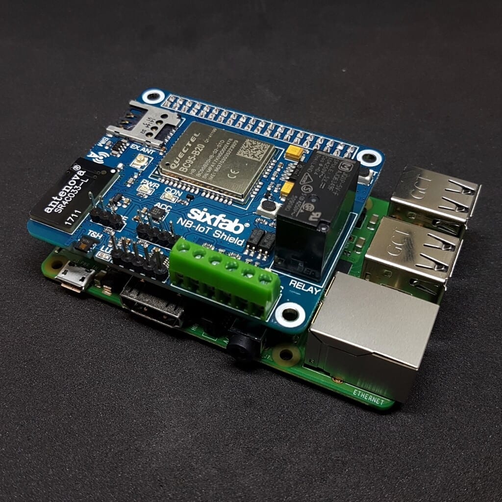
LTE Cat NB1(NB-IoT) is a more modern and advanced way of Machine-to-machine communication than legacy GPRS connection. In comparison with GPRS, the NB-IoT connection has extremely low power consumption and is much more efficient. This Narrowband-IoT shield allows you to connect your Raspberry Pi to this new cellular network with the help of Quectel’s BC95 NB-IoT module.
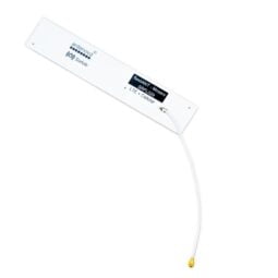
Quectel BC95 is a high-performance LTE NB-IoT module offering a maximum data rate of 21.25Kbps downlink and 15.625kbps uplink. The NB-IoT shield has built-in temperature, humidity, light sensors, 3-axis accelerometer, a relay and more. Built-in SMD antenna lets you establish the connection right out of the package.
Features
- Fully compatible with Raspberry Pi models that have the 40-pin GPIO header (3, 2, B+, A+, Zero)
- Supported Protocol Stacks: IPv4/UDP/CoAP/LwM2M/Non-IP
- Frequency Band: EUROPE region coverage with the B20-800MHz band
- 12-Bit 4 Channel ADC
- 3-axis Accelerometer
- Humidity and Temperature Sensors
- Ambient Light Sensor
- Isolated Optocoupler Inputs
- 1-Wire Sensors Interface
- 3GPP TS 27.007 V14.3.0 and Quectel Enhanced AT Commands over UART port to Raspberry Pi is available
- Efficient and low quiescent current regulator circuit can hold up to 3.6A
- Micro SIM Card socket is easily reachable on the upside of the shield.
- Working temperature range: -30°C to +80°C
Key Applications
- Smart farming sensor
- Smart cities sensor
- Smart home sensor
- Internet of Things (IoT) sensor
- Smart door lock
- Smart lighting
- Smart metering
- Smart parking
- Smart city
- Home appliances
- Agricultural and environmental monitoring
Technical Details
Connection Types
UART: The UART pins are available to use, with 3.3V power domain, directly connected the 9600bps baud rate. The default data frame format is 8N1 (8 data bits, no parity, 1 stop bit).
Data Speeds
Downlink: 21.25Kbps @Single Tone
Uplink: 15.625kbps @Single Tone
Power Consumption (Typical)
- 3.6uA @PSM
- 2mA @Idle Mode, DRX=1.28s
- LTE Cat NB1 Connectivity:
- 220mA @Radio Transmission, 23dBm (B8/B5/B20)
- 100mA @Radio Transmission, 12dBm (B8/B5/B20/B28)
- 70mA @Radio Transmission, 0dBm (B8/B5/B20/B28)
- 65mA @Radio Reception
SMS
Point-to-point MO and MT
Text and PDU Mode
Enhanced Features
- DFOTA: Delta Firmware Upgrade Over the Air
- RAI: Release Assistance Indication
Warnings
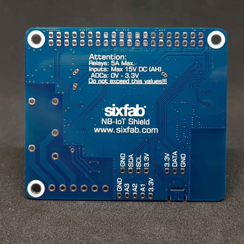
Do not apply higher voltages and currents than those specified absolute electrical value for sensor inputs and relay connections.
Electrical
Pinout

Pin Descriptions
| Pin Number | BCM Pin | Pin Name | Description |
|---|---|---|---|
| 2 | 5V | 5V PWR | This pin is connected to the 5V power net. |
| 3 | GPIO 2 | SDA | I2C Serial Data |
| 4 | 5V | 5V PWR | This pin is connected to the 5V power net. |
| 5 | GPIO 3 | SCL | I2C Serial Data |
| 7 | GPIO 4 | 1-WIRE | Data line to communicate with 1-Wire sensors. |
| 8 | UART RX | BC95 TX | This pin functions as the serial data input to the module for UART communication. |
| 10 | UART TX | BC95 RX | This pin functions as the serial data output from the module for UART communication |
| 29 | GPIO 5 | IN-2 | When the voltage in the range 3.3-12V(max 15V!) is applied from the IN-2 input, this pin goes to LOW state. The default state is HIGH(pulled-up). |
| 31 | GPIO 6 | VDD_EXT | When BC95 powered on, VDD EXT pin switched to HIGH level. You can detect BC95 ON/OFF state by reading this pin. |
| 32 | GPIO 12 | IN-1 | When the voltage in the range 3.3-12V(max 15V!) is applied from the IN-1 input, this pin goes to LOW state. The default state is HIGH(pulled-up). |
| 36 | GPIO 16 | RESET | Reset the module by driving the reset pin to a HIGH-level voltage for +100ms at least. |
| 37 | GPIO 26 | RELAY | Relay control pin. When this pin is HIGH state, the relay is operated.(COMMON and NO will be connected.) |
| 38 | GPIO 20 | USER LED | Active HIGH, to switch on the USER LED, the pin’s state should be HIGH. |
| 40 | GPIO 21 | USER BUTTON | This pin is pulled-up by default. When the button is pressed, pin switches to LOW. |
| 6,9,14,25,30,34,39 | GND | GND | These pins are connected to ground. |
Electrical Characteristics of Pins
| Pin Number | BCM Pin | Pin Name | Description | Min | Typ. | Max. | Unit |
|---|---|---|---|---|---|---|---|
| 2 | 5V | 5V PWR | Power Supply | 4.8 | 5 | 5.25 | V |
| 3 | GPIO 2 | SDA | I2C Data | 3 | 3.3 | 3.6 | V |
| 4 | 5V | 5V PWR | Power Supply | 3 | 3.3 | 3.6 | V |
| 5 | GPIO 3 | SCL | I2C Clock | 3 | 3.3 | 3.6 | V |
| 7 | GPIO 4 | 1-WIRE | 1-Wire data | 3 | 3.3 | 3.6 | V |
| 8 | UART RX | BC95 TX | UART | 3 | 3.3 | 3.6 | V |
| 10 | UART TX | BC95 RX | UART | 3 | 3.3 | 3.6 | V |
| 29 | GPIO 5 | IN-2 | Input | 3 | 3.3 | 3.6 | V |
| 31 | GPIO 6 | VDD_EXT | Input | 3 | 3.3 | 3.6 | V |
| 32 | GPIO 12 | IN-1 | Input | 3 | 3.3 | 3.6 | V |
| 36 | GPIO 16 | RESET | Output | 3 | 3.3 | 3.6 | V |
| 37 | GPIO 26 | RELAY | Output | 3 | 3.3 | 3.6 | V |
| 38 | GPIO 20 | USER LED | Output | 3 | 3.3 | 3.6 | V |
| 40 | GPIO 21 | USER BUTTON | Input | 3 | 3.3 | 3.6 | V |
Layout

Schematic
You can download the schematic of Raspberry Pi NB-IoT Shield from this Github repository.
LEDs
- POWER (PWR): When the shield&module is powered up, this RED led turns on.
- USER (USER): The GREEN user led can be controlled by driving the GPIO 27 pin.
- CONNECTION (CON) : This BLUE led indicates the status of the module. When the connection is established and data is being transmitted/received, this led will blink at special intervals. This feature of the module is under development, will be activated on future firmware.
Buttons
- USER: This push button connected to GPIO21 and pulled up HIGH state by default. When you push the button, you will read LOW state from GPIO21.
- RESET: When the BC95 is in powered on, it can be reset by pushing the RESET button for at least 100ms. Also, driving GPIO16 to the HIGH state will cause a reset.
3-axis 12-bit/8-bit Digital Accelerometer | MMA8452Q
- The MMA8452Q is a smart, low-power, three-axis, capacitive, micromachine accelerometer with 12 bits of resolution. It has user selectable full scales of ±2 g/±4 g/±8 g with high-pass filtered data as well as non-filtered data available real-time.
- The accelerometer connected to Raspberry Pi via I2C. The I2C address is 0x1C.
- MMA8452Q’s interrupt pins are not connected.

12-Bit Analog-to-digital Converter | ADS1015
- The ADS1015 is precision, low-power, 12-bit, an analog-to-digital converter.
- Raspberry Pi can not measure analog inputs because it does not have internal ADC. However, with this external ADC, the ADS1015, you can read analog values with your Raspberry Pi.
- The ADC connected to Raspberry Pi via I2C. The I2C address is 0x49.
Ambient Light Sensor | ALS-PT19
- It’s a phototransistor close responsively to the human eye spectrum, light to current.
- It’s connected to ADC (ADS1015) as its analog output cannot be read directly by Raspberry Pi.
- The sensor connected to AIN0 pin of ADS1015.
Temperature and Humidity Sensor | HDC1080
- The HDC1080 is a digital humidity sensor with integrated temperature sensor that provides excellent measurement accuracy at very low power.
- Relative Humidity Accuracy ±2% (typical)
- Temperature Accuracy ±0.2°C (typical)
- The HDC1080 connected to Raspberry Pi via I2C. The I2C address is 0x40.
- The heat produced by R.Pi heating up may cause the sensor to display a few higher degrees than the ambient temperature.
Relay
- The relay for controlling high voltage and current.
- Relay control pin is GPIO37. When this pin is HIGH, the relay is switched and connected C and NO pins. When GPIO37 is LOW state or unused, it connects C and NC pins.WARNING! : This relay and traces can handle up to 120W or 5 Amps. Pushing the limits will produce heat and definitely harm the circuits and shield. Recommended maximum contact ratings:
- 12V DC – 5A
- 24V DC – 5A
- 120V AC – 1A
- 220V AC – 0.5A
Isolated Inputs
- Two isolated by optocouplers inputs available on the shield. Recommended max. GPIO voltage level of Raspberry Pi is 3.3V. Reading higher than 3.3V voltage inputs are harmful to your Pi and will definitely destroy the circuits.
- The upper limit of these inputs is 15V, between 3.3V and 15V is readable. GPIO pins are normally pulled up, when a voltage applied to isolated inputs, GPIO pins go LOW state.
- The input’s (sensor, switch etc) ground must be connected to optocoupler’s G input to complete the isolated circuit.
External I2C Header
When you need to add an external I2C thing, you can use these I2C connectors. 3.3V VCC and GND pins provided too. It has pull-up resistors.
1-Wire Header
There are lots of sensors which have 1-Wire connection standard (DS18B20 etc.) in the market. The 1-Wire connector has VCC, DATA and GND pins. You can easily connect a 1-wire sensor with these pins. Data pin directly connected to GPIO4 and has a 4.7K pull-up resistor.
Mechanical

3D Design Files
You can download the 3D design files(STEP, IGES) of the Sixfab Raspberry Pi NB-IoT Shield from this Github repository.
Package Includes
- 1x Sixfab Raspberry Pi NB-IoT Shield
- 1x Mini Flat Head Screwdriver for Connection Terminals
Instructions
You may find your questions in F.A.Q under support menu. If you didn’t find the answer to your question, please feel free to ask us via contact form.
Tutorials
User Manuals
- Download Quectel BC95 AT Commands Manual v2.0
- Download Quectel BC95 DFOTA User Guide v1.0
- Download Quectel BC95 Release Notes and FAQs v1.5
Datasheets
- Download HDC1080 Temperature&Humidity Sensor Datasheet
- Download MMA8452Q 3-Axis Accelerometer Datasheet
- Download ADS1015 12-Bit 4-Ch ADC Datasheet
- Download ALS-PT19 Light Sensor Datasheet
Github Repository
The Raspberry Pi NB-IoT Shield Github Repository contains the libraries and codes are used in tutorials, hardware files and more.